Buy COLORFUL BATTLE-AX B450M-K M.2 V14 Motherboard in Pakistan | TechMatched
₨22,500.00
About this item
- Supports AMD AM4 Ryzen
- 2x DIMMs, DDR4-4000(OC)
- HDMI+VGA Display Interface
- 1x PCIe 3.0 x4 M.2 SSD Slot
Warranty!
10 Months Warranty
Avail Free delivery on Bank Transfer
Description
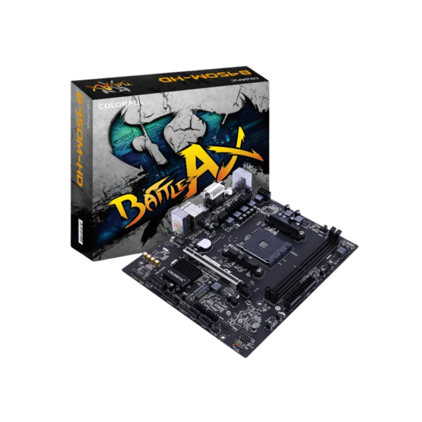
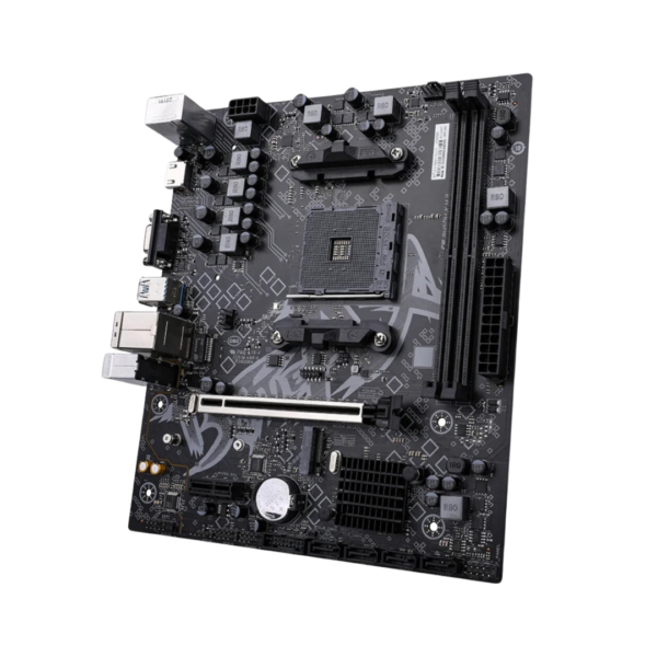
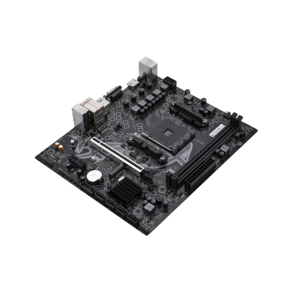
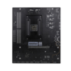
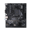
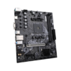
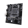
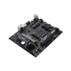
Colorful BATTLE-AX B450M-K M.2 V14 AMD AM4 microATX Motherboard
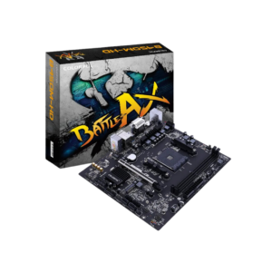
- Supports AMD AM4 Ryzen
- 2x DIMMs, DDR4-4000(OC)
- HDMI+VGA Display Interface
- 1x PCIe 3.0 x4 M.2 SSD Slot
Features
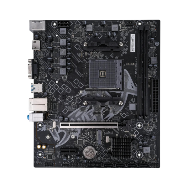
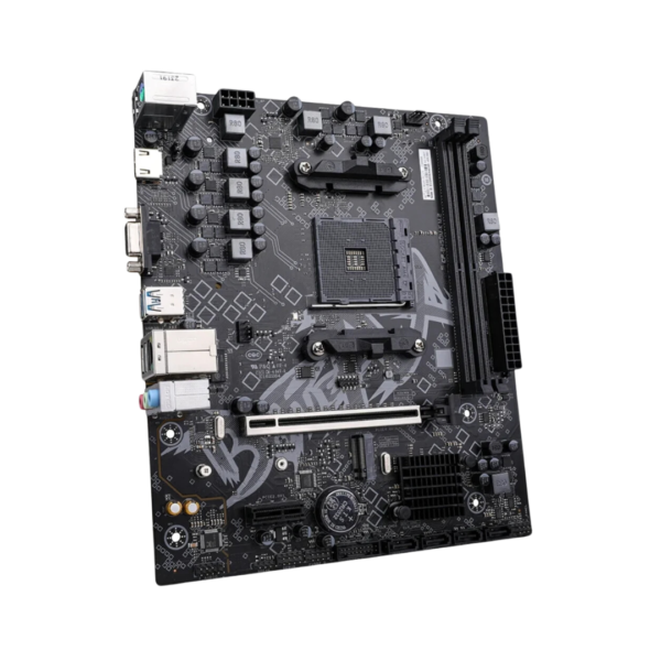
- Provide 1 PCIe 3.0 x4 M.2 SSD slot
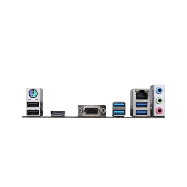
- Provide 4 USB 3.2 Gen 1 Type-A high-speed rear interfaces
- Provide 2 USB 2.0 interfaces
- Equipped with RTL8111H Gigabit wired network card
- Provide HDMI+VGA display interface
- Six major protective technologies ensure more stable product operation
- Strict testing of 200 processes with guaranteed quality
- Comprehensive upgrade of PCB atomization process
Specifications
| Model | BATTLE-AX B450M-K M.2 V14 |
|---|---|
| Product Series | BATTLE-AX series |
| Chipset | AMD B450 |
| Processor | Supports AMD Ryzen series processors that fit the AMD AM4 slot of the motherboard (* Please visit www.colorful.cn for the latest memory compatibility list) |
| Memory | 2 DDR4 memory sockets are provided, which can support up to 64GB of memory (a single socket can support up to 32 GB of memory) – Support DDR4-4000(OC)/3733(OC)/3600(OC)/3466(OC)/3200(OC)/3000(OC)/2933(OC)/2800(OC)/2666/2400/2133MHz memory – Support Extreme Memory Profile (XMP) memory technology – Supports dual channel memory technology (* Please visit www.colorful.cn for the latest memory compatibility list) |
| SATA Ports | 1 M.2 slot and 4 SATA 6Gb/s hard disk interfaces – M.2_1 slot: supports 2242/2280 M.2 SSD (PCIe 3.0 x4/SATA, CPU channel) |
| Board I/O | Rear I/O : -2×USB 2.0 interfaces -4×USB 3.2 Gen 1 Type-A interfaces -1×HDMI 2.0 interface, Supports up to 4K 60Hz resolution -1×VGA interface -1×PS/2 interface -1×Gigabit network interface -3×Audio interfaces (audio input/audio output/microphone) On board: -1×CPU fan pin -1×System fan pin -1×USB 2.0 pin expandable 2 USB 2.0 Type-A interfaces -1×USB 3.2 Gen 1 pin expandable 2 USB 3.2 Gen 1 Type-A interfaces -1×Front audio pin -1×Front panel pin -1×Speaker pin -1×Digital audio pin -1×Clear CMOS jumper -1×BIOS burner pin -1×Debug light pin -1×USB live control jumper |
| Expansion Slots | 1×PCIe 3.0 x16 slot 1×PCIe 2.0 x1 slot |
| BIOS | 128M UEFI, support multiple languages |
| Power Management | Support S3/S4 wake-up, network S5 wake-up, support USB wake-up, support timing boot, call boot |
| Hardware Monitor | CPU fan speed is controllable, system fan speed is controllable, CPU temperature monitoring, system temperature monitoring, and each group of voltage monitoring |
| LAN | RTL8111H Gigabit Network Card |
| Audio | Realtek ALC897 high fidelity decoding chip, Support up to 5.1 channels |
| Configuration | M-ATX 230mm x 197mm |
Pins and Jumpers
CPU fan pin (CPU_FAN)
There is one 4-pin CPU fan pin on the motherboard. The socket comes
with a foolproof design, and the correct direction must be checked before
installation. The cooling fan with a speed control function can reduce the
temperature of the CPU and provide cooling function, improve CUP stability.
System fan pin (CHA_FAN)
The motherboard provides one 4-pin system fan sockets which has
foolproof design and please pay attention to the direction when installing.
The cooling fan with the rotating speed control function can lower the
temperature in the chassis and help the chassis to dissipate heat.
Front USB 2.0 pin (FUSB2.0)
There is one front USB 2.0 expansion pin on the motherboard, which can be
expanded to two USB 2.0 interfaces.
Front USB 3.2 Gen 1 pin (FUSB3.0)
There is one front USB 3.2 Gen 1 expansion pin on the motherboard, which
can be expanded to two USB 3.2 Gen 1 Type-A and it’s compatible with USB
2.0 devices.
Front audio pin (F_AUDIO)
The audio interface on the front panel of the case can be connected to
the front audio pin through the audio cable in the case, allowing audio
input/output and other functions through the audio interface on the front
panel.
Front panel pin (F_PANEL)
PWR_Switch:Power switch, short connect to be power on.
Reset_Switch:Restart switch, short connect to restart the computer.
PWR_LED:Power indicator.The LED will light up when the power is on.
HD_LED:Hard disk indicator. The LED will light up when the hard disk
is accessing data.
Speaker pin (SPEAK)
Speaker pin can be used to connect speakers located in the case.
Digital audio pin (JSPDIF)
There is one digital audio pin on the motherboard, which can be used to connect the digital
audio output module.
Clear CMOS jumper (CLR_CMOS)
Clear CMOS jumper can be used to clear data in the CMOS memory of the motherboard. In
CMOS memory it stores the BIOS setting parameters and is powered by the battery on the
main board independently. If you need to clear CMOS data, first turn off the computer and
unplug the power cord, insert the jumper cap onto the CMOS pin, and make the two pins
Short connect the feet for 5 seconds, then pull out the jumper cap, wait for 5
minutes, and then start the computer to enter the BIOS Reset BIOS parameters.
BIOS burner pin (JBIOS)
BIOS burner pins can be used to upgrade the motherboard BIOS by connecting to the BIOS
burner.
Debug light pin (DEBUG)
The debug light pin can be used to connect to the motherboard debug light, And analyze
the cause of abnormal motherboard based on the status displayed by the debugging light.
USB live control jumper (JKB)
The USB powered control jumper can control whether the two USB 2.0 interfaces
below the PS/2 interface are powered off. When the motherboard leaves the factory,
the two USB 2.0 interfaces below the PS/2 interface are not charged by default,
and the jumper caps are inserted on pins ① and ②. If you need to power up two
USB 2.0 interfaces, first turn off the computer and unplug the power cord. Pull
out the jumper cap and plug it into pins ② and ③, and then reconnect the power
cord. At this time, both USB 2.0 interfaces are in a live state.
For further details, visit official website.
“TechMathced offers a price-match policy for its customers. If you find anyone selling at less price than us, you can simply contact us and we’ll match the price for you.
Read here in detail about Price-Match Policy.”
Additional information
| Weight | 1 kg |
|---|---|
| Warranty | 1-Year |

Reviews
There are no reviews yet.